Dot matrix control pcb – PinLED A-14039
£120.95
3 in stock (can be backordered)
Description
Absolutely new development of the Dot Matrix Controller Board A-14039 / A-14039-1. Our PinLED Dot Matrix Controller Board is a replacement for defective original boards. The board has brand new innovations and has this two advantages:
-
New Digital Section
-
New Power Supply Section
It is possible to go new ways in circuit board design with new parts. We use the most modern parts on this board and this will help us to eliminate all of the bad failures that you can find on the old boards.
-
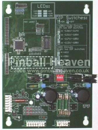
The new development of the digital section: As you can see on the left picture below at that time (beginning of the 90th) it wasn’t possible to use the modern technique of today. The board was a “TTL grave”. The Williams designer used over 33 ICs (A-14039) or rather 34 ICs (A-14039-1) plus one CMOS RAM. This was 520 (plus 28 for the CMOS RAM) IC- pins to solder with the board. All these soldering pads are potential sources of errors. Quite apart from the troubleshooting in this section of the original board. Quite often the fault was found after the fifth or sixth change of a IC. What a waste of time and money! With the state of the art technique of today it is possible to use programmable ICs. It is possible to summarize all the functions of the original 33 or 34 ICs on one chip. We use a modern IC called PLD on our board and this PLD has only 100 pins. We have removed consistently all the mistakes of the original design. We have changed the original asynchronous design to a much more better running synchronous design.
-
The new development of the power supply: We have halve the number of parts in the power supply section on our Dot matrix Controller Board. In the original design from Williams they used eight transistors to produce the three supply voltages. On our board only two high- voltage adjustable regulators are in charge for the production of the three voltages. On our board it is possible to adjust the output voltages with four dip switches. With this feature you can adjust each voltage in four steps (e.g. for the -125 Volt you can adjust the voltage between -112 to -125V). With this feature it is possible to drive old displays with a higher voltage and new displays with a lower voltage. There are also six LEDs on our board to display the availability of each voltage level (+3,3V, +5V, +12V, +62V, -113V, – 125V). With them it is easy to locate the voltage section for missing voltages.
-
INSTALLATION INSTRUCTIONS – http://www.pinled.de/pages/support/english/10031.php
Additional information
| Weight | 1 g |
|---|
Related products
-
Tapered Yellow Post
£1.98 Add to basket -
3″ Rubber Ring
£0.79 Select options This product has multiple variants. The options may be chosen on the product page -
2 1/2″ Rubber Ring
£0.66 Select options This product has multiple variants. The options may be chosen on the product page -
Yellow Post Sleeve
£0.70 Add to basket