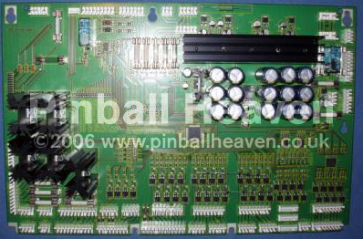
Power driver board – A-12697-x
£ 384.94
Out of stock
Description
This board does NOT work with LED lamps!
Absolutely new development of the WPC Driver Board A-12697-1 / A-12697-2 / A12697-3. PinLED WPC Driver Board is a replacement for defective original boards. The board has brand new innovations and has this advantages:
-
New Digital Section
-
New Driver Section
-
Switch-On-Current-Limiter
-
New Switched 5Volt Power Supply
-
New 12 Volt Digital Power Supply
-
Using of Low impedance capacitors
-
LEDs and test points are close together to make monitoring much easier
-
LEDs to monitor the solenoid fuses
-
Layout print with the values of the fuses and names
-
Thicker wiring of the driver section
-
Larger heat sinks for the Gen. Illumination
-
Larger heat sinks for the rectifier and power section
It is possible to go new ways in circuit board design with new parts. We use the most modern parts on this board and this will help us to eliminate all of the bad failures that you can find on the old boards.
-
New Digital Section: We use for our board a CPLDs (Complex Programmable Logic Device). With this CPLD it is possible to reduce the number of used ICs. In this way we can go without the old ICs of the 74 family. This decreases the number of pins to solder and eliminates the sources of broken ICs.
-
New Driver Section: We use for our board MOSFETs instead of normal bipolar transistors. This reduces also the number of parts dramatically. In the original design there are two to three transistors used for each driver channel. Now only one MOSFET does the job. We also changed the transistors of the lamp matrix to MOSFETs. What is the advantages of the MOSFETs instead of using normal bipolar transistors? MOSFETs have a very small on-resistance. Which means they can transfer a lot more power with less losses as normal bipolar transistors. This has the benefit that the MOSFET produce much less heat. The original used transistors TIP 102, 107 and 36C become very hot as soon as the switch-on-time is longer. The result is that the bipolar transistor dies the “heat death”. Now even with bad coils or with shorted circuits it is not possible to destroy the MOSFETs because the fuses have now enough time to trip and the MOSFET will survive.
-
Switch-On-Current-Limiter: Very often it happens that the rectifier of the original Bally/Williams board dies because of its very high switch-on-current. Why die the rectifiers so often? Because of the huge value of the directly following capacitors (15,000 or 30,000µF). For the rectifiers this large value of the capacitors looks in the very first moment as a short circuit. Only a few moments later (milliseconds) the current drops to a smaller value because the capacitors have reached a certain voltage level. But in the very first moment the value of the current is two to three times larger than the maximum rate of the rectifier. The rectifiers have a value of 35A but in the very first moment currents up to 60 – 90A are possible. We included on our board a soft start circuit for the four rectifiers that drive the huge capacitors. In this way the peaks of the switch-on-current is in normal borders.
-
New Switched 5 Volt Power Supply: The original 5V/3A power supply reaches very often its upper limit of the power performance. We changed it to a switched 5V/5A power supply. The big advantage of using a switched power supply is that this kind of power supply has a much higher efficacy towards an linear regulator. And it produces much less heat as the normal regulator.
-
New 12 Volt Digital Power Supply: With our new 12 Volt Digital power supply you are now independent from the 18 Volt switched lamp power source. In the original Williams design the 18 Volt for the controlled lamps also sources the 12 Volt digital power supply. This has the negative consequence that the input voltage level for the 12 Volt regulator is always changing and therefore the output too. In our design the 12 Volt power supply also drives the 12 Volt Digital power supply. Now you can measure exact 12 volts at the output of our low drop 12 volt regulator without a changing level.
-
We are using high quality low impedance capacitors: These capacitors have a very small ESR and a temperature range up to 105°C. That means our used capacitors have a very long lifetime so dry out capacitors belong to the past.
-
LEDs and test points are close together to make monitoring much easier: All LEDs are close together to make the monitoring more easier for you. So you will find them earlier and this helps you to make your troubleshooting faster and safer.
-
LEDs to monitor the solenoid fuses: The fuses for the solenoids have LEDs for easy troubleshooting. You can see immediately if a fuse is bad and the change is therefore much easier for you (F101 to F105).
-
Layout print with the values of the fuses and names: We added a print on the board with all value of the used fuses. Now you do not have to worry about the manuals and finding the right values for the fuses.
-
Thicker wiring of the driver section: All wires on the board are stronger to handle the amount of the current. This has also the advantage that the heat can better flow away from the board and burned out wires belong to the past.
-
Larger heat sinks for the Gen. Illumination: On the original Williams WPC driver board are small heat sinks for the five Triacs (Gen. Illumination) installed. We are using much bigger heat sinks because the Triacs have a powerful job to do. We changed the original heat sinks (38.1mm height / Rw = 6.5 K/W) to the largest ones (50.8mm height / Rw = 5.3 K/W). Now the Triacs produce about 20% less heat than before.
-
Larger heat sinks for the rectifier and power section: We also added larger heat sinks to the rectifiers and the power section. All rectifiers stay now stay cool and are working in a safe temperature range.
Additional information
| Weight | 2001 g |
|---|---|
| Compatibility |

